| “This site contains affiliate links for which OEMDTC may be compensated” |
L-SB-0116-08
September 17, 2008
Rear Driveshaft/Propeller Shaft Clunk/Thump Noise
| Service Category | Drivetrain | ||
|---|---|---|---|
| Section | Drive Shaft/Propeller Shaft | Market | USA |
Applicability
| YEAR(S) | MODEL(S) | ADDITIONAL INFORMATION |
|---|---|---|
| 2003 – 2008 | GX470 | VDS(s): BT20X |
| TSIB SUPERSESSION NOTICE
The information contained in this TSIB supersedes TSIB No. DL002-07.
TSIB No. DL002-07 is Obsolete and any printed versions should be discarded. Be sure to review the entire content of this service bulletin before proceeding. |
Introduction
Some owners of 2003 – 2008 model year GX 470 vehicles may experience a clunk/thump noise from the rear of the vehicle or a “bump-from-behind” sensation just before or after coming to a stop. A new propeller shaft assembly has been developed and implemented in production to improve this condition.
Production Change Information
This TSIB applies to vehicles produced BEFORE the Production Change Effective VIN shown below.
| MODEL | PRODUCTION CHANGE EFFECTIVE VIN |
|---|---|
| GX 470 | JTJBT20X*80170241 |
Parts Information
| PREVIOUS PART NUMBER | CURRENT PART NUMBER | PART NAME | QTY |
|---|---|---|---|
| 37110-6A480 | 37110-60A40 | Shaft Assembly, Propeller | 1 |
Warranty Information
| OP CODE | DESCRIPTION | TIME | OFP | T1 | T2 |
|---|---|---|---|---|---|
| 370011 | R & R Rear Driveshaft Assembly | 0.5 | 37110-6A480 | 91 | 50 |
APPLICABLE WARRANTY
|
Repair Procedure
- Test drive vehicle and confirm noise condition.
| NOTE
Check for the painted matchmarks on the transfer flange and differential flange when installing the NEW propeller shaft assembly. If the matchmarks are NOT visible, be sure to install the NEW propeller shaft in the same orientation as the original propeller shaft. |
- Remove and replace the 2-piece propeller shaft assembly.
Refer to the Technical Information System (TIS):
- 2003 / 2004 / 2005 GX 470: Drivetrain – Driveshaft/Propeller Shaft – “Propeller Shaft Assy: Overhaul”
- 2006 / 2007 / 2008 GX 470: Drivetrain – Driveshaft/Propeller Shaft – “Propeller Shaft Assy: Removal”
- 2006 / 2007 / 2008 GX 470: Drivetrain – Driveshaft/Propeller Shaft – “Propeller Shaft Assy: Installation”
A. Remove the propeller shaft assembly.
(1) Remove the 4 nuts and 4 washers (propeller shaft to transfer flange).
Figure 1.
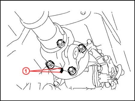
| 1 | Matchmarks | |
(2) Remove the 4 nuts, 4 bolts, and 4 washers and then the propeller shaft assembly (propeller shaft to differential flange).
Figure 2.
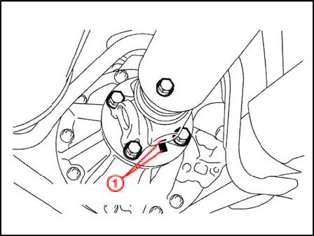
| 1 | Matchmarks |
B. Install the NEW propeller shaft assembly.
(1) Align the matchmarks on the yoke and the differential flange.
Figure 3.
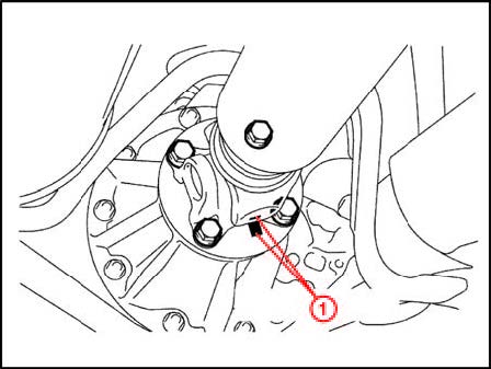
| 1 | Matchmarks |
(2) Install the propeller shaft assembly with the 4 bolts, 4 nuts, and 4 washers. Torque: 88 N*m (898 kgf*cm, 65 ft*lbf)
(3) Align the matchmarks on the yoke and the transfer flange.
Figure 4.
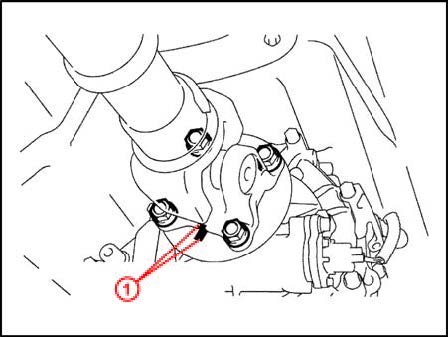
| 1 | Matchmarks |
(4) Install the propeller shaft assembly with the 4 nuts and 4 washers. Torque: 88 N*m (898 kgf*cm, 65 ft*lbf)
- Test drive vehicle and confirm repair effectiveness.
 Loading...


