| “This site contains affiliate links for which OEMDTC may be compensated” |
T-SB-0138-10
May 28, 2010
Transmission Fluid or Gear Oil Seepage from Transfer Case Vent (AWD)
Service Category
Drivetrain
Section
Transfer/4wd/Awd
Market
USA
Applicability
| YEAR(S) | MODEL(S) | ADDITIONAL INFORMATION |
|---|---|---|
| 2004 – 2009 | Highlander | Drive Type(s): 4WD Engine(s): 3MZ, 2GR, 2AZ
Transmission(s): 4AT, 5AT VDS(s): EP21A, ES41A, ES42A, ES43A, HD21A, HP21A WMI(s): JTE |
| 2001 – 2005 | RAV4 | Drive Type(s): 4WD Engine(s): 2AZ, 1AZ
Transmission(s): 4AT VDS(s): HD20V, HH20V WMI(s): JTE |
| 2004 – 2010 | Sienna | Drive Type(s): 4WD Engine(s): 3MZ, 2GR
Transmission(s): 5AT VDS(s): BA22C, BA23C, BK22C, BK23C, DK4CC, JK4CC WMI(s): 5TD |
TSB SUPERSESSION NOTICE
The information contained in this TSB supersedes TSB No. TC008-07.
- Applicability has been updated to include 2007 – 2009 Highlander, 2001 – 2005 RAV4, and 2007 – 2010 Sienna vehicles.
TSB No. TC008-07 is Obsolete and any printed versions should be discarded. Be sure to review the entire content of this service bulletin before proceeding.
Introduction
Some 2004 – 2009 model year Highlander, 2001 – 2005 model year RAV4, and 2004 – 2010 model year Sienna AWD (4WD) vehicles may display a transmission fluid or gear oil seepage from a vent on the right side of the transfer case. The seepage is from the transfer RH (right-hand) bearing retainer No. 2 oil seal. Production improvements have been implemented to prevent this condition from occurring. Follow the repair procedure in this bulletin to replace the RH bearing retainer No. 2 oil seal assembly.
Production Change Information
This TSB applies to 2001 – 2005 RAV4 and to Highlander and Sienna vehicles produced BEFORE the Production Change Effective VINs shown below.
| MODEL | PLANT | DRIVETRAIN | PRODUCTION CHANGE EFFECTIVE VIN |
|---|---|---|---|
| Highlander | TMK1 | AWD | JTEES4#A#92137597 |
| Sienna | TMMI | AWD | 5TD#K4CC#AS028750 |
Warranty Information
| OP CODE | DESCRIPTION | MODEL YEAR | MODEL | TIME | OFP | T1 | T2 |
|---|---|---|---|---|---|---|---|
| TC7004 | R & R Transfer RH Bearing Retainer No. 2 Oil Seal | 2001–2005 | RAV4 (M/T) | 11.5 | 90316-37001 | 65 | 57 |
| RAV4 (A/T) | 13.6 | ||||||
| 2004–2006 | Highlander (4 cylinder) | 9.7 | |||||
| Highlander (V6) | 10.3 | ||||||
| Sienna | 10.2 | ||||||
| 2007–2009 | Highlander (V6) | 11.9 | |||||
| 2007–2010 | Sienna | 9.3 |
APPLICABLE WARRANTY
- This repair is covered under the Toyota
 Powertrain Warranty. This warranty is in effect for 60 months or 60,000 miles, whichever occurs first, from the vehicle’s in-service date.
 - Warranty application is limited to occurrence of the specified condition described in this bulletin.
Parts Information
| PREVIOUS PART NUMBER | CURRENT PART NUMBER | PART NAME | QTY |
|---|---|---|---|
| 90316-37001 | Same | Seal, Oil, No. 2 (for Transfer RH Bearing Retainer) | 1 |
90301-70002 | Same | Ring, O | 1 |
| 90311-34021 | Same | Seal, Oil, No. 1 (for Transfer RH Bearing Retainer) | 1 |
| 12157-10010 | Same | Gasket | 3 |
| 90301-11018 | Same | Ring, O | 1 |
| 36141-21010 | Same | Gasket, Transfer Cover | 1 |
| 90366-38020 | Same | Bearing, Tapered Roller | 1 |
Required Tools & Equipment
| REQUIRED MATERIAL | CLASSIFICATION | QUANTITY | ||
|---|---|---|---|---|
| Transfer Case Oil | Hypoid Gear Oil SAE 90 (GL-5) | 0.95 U.S. qts (0.9 liters) | ||
| Transmission Fluid | ATF Type T-IV | 3.8 U.S. qts (3.6 liters) | ||
| ATF WS | ||||
| FIPG Sealant: Three Bond 1281, or equivalent | – | As needed | ||
| MP Grease | – | As needed | ||
| SPECIAL SERVICE TOOLS (SST’S) | PART NUMBER | QTY | ||
|---|---|---|---|---|
| Oil Seal Puller (or equivalent) | 09308-00010 | 1 | ||
| Transmission Housing Remover* | 09520-10021 | 1 | ||
| Crankshaft Front Oil Seal Replacer* | 09223-46011-01 | 1 | ||
| RH Bearing Retainer Installer* | 09387-00090 | 1 | ||
| Output Shaft Nut Wrench (or equivalent) | 09326-20011 | 1 | ||
| Bearing Remover (or equivalent) | 09950-00020 | 1 | ||
| Differential Drive Pinion Holding Tool 28* | 09556-16030-01 | 1 | ||
| Replacer Set #1*
(Replacer 36) (Replacer 54) (Replacer 62) (Adapter) | 09950-60010-01
(09951-00360-01) (09951-00540-01) (09951-00620-01) (09952-06010-01) | 1 | ||
| Handle Set*
(Handle Assembly 150 – 6.25 inch) | 09950-70010-01
(09951-07150-01) | 1 | ||
| Plastic Pry Tool Set* | 00002-06000-01 | 1 | ||
* Essential SST.
NOTE
Additional SSTs may be ordered by calling 1-800-933-8335.
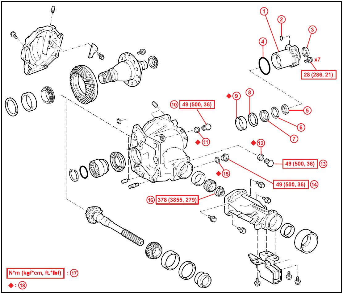
Components
Figure 1.
| 1 | RH Bearing Retainer Sub-assembly | 10 | No. 2 Plug |
| 2 | RH Bearing Retainer O-ring | 11 | Gasket No. 2 |
| 3 | RH Bearing Retainer Oil Seal No. 1 | 12 | Gasket No. 1 |
| 4 | O-ring | 13 | No. 1 Plug |
| 5 | Side Gear Shaft Holder Bearing | 14 | Drain Plug |
| 6 | Snap Ring | 15 | Drain Gasket |
| 7 | RH Bearing Retainer Oil Seal No. 2 | 16 | Lock Nut |
| 8 | Ring Gear Mounting Case Washer No. 2 | 17 | Specified Torque |
| 9 | Center Differential Case Tapered Roller Bearing RH (Outer Race) | 18 | Non-reusable Part |
Repair Procedure: Removal
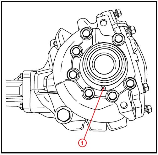
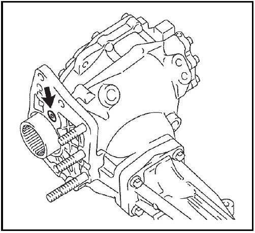
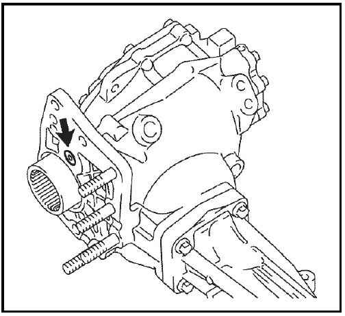
- Confirm source of gear oil/transmission fluid seepage is from vent on RH bearing retainer.
Figure 2.
| 1 | Location of Seepage in RH Bearing Retainer (Vent) |
Refer to the Technical Information System (TIS), applicable model and model year Repair Manual:
- 2004 Highlander: Engine/Hybrid System – Engine Mechanical – “2AZ-FE / 3MZ-FE: Partial Engine Assy: Replacement”
- 2005 Highlander: Engine/Hybrid System – Engine Mechanical – “2AZ-FE / 3MZ-FE: Partial Engine Assy: Replacement”
- 2006 Highlander: Engine/Hybrid System – Engine Mechanical – “2AZ-FE / 3MZ-FE Engine Mechanical: Engine Assembly: Removal”
- 2007 Highlander: Engine/Hybrid System – Engine Mechanical – “2AZ-FE / 3MZ-FE Engine Mechanical: Engine Assembly: Removal”
- 2008 / 2009 Highlander: Engine/Hybrid System – Engine Mechanical – “ 2GR-FE Engine Mechanical: Engine Assembly: Removal”
- 2001 / 2002 / 2003 / 2004 / 2005 RAV4: Engine/Hybrid System – Engine Mechanical – “Engine Unit: Removal”
- 2004 / 2005 Sienna: Engine/Hybrid System – Engine Mechanical – “3MZ-FE: Partial Engine Assy: Replacement”
- 2006 Sienna: Engine/Hybrid System – Engine Mechanical – “3MZ-FE Engine Mechanical: Engine Assembly: Removal”
- 2007 / 2008 / 2009 / 2010 Sienna: Engine/Hybrid System – Engine Mechanical – “2GR-FE Engine Mechanical: Engine Assembly: Removal”
- Remove the automatic transmission w/transfer.
Refer to TIS, applicable model and model year Repair Manual:
- 2004 Highlander: Drivetrain – Automatic Transmission/Transaxle – “Automatic Transaxle Assy (U151E/U151F) / (U241E/U140F): Replacement”
- 2005 Highlander: Drivetrain – Automatic Transmission/Transaxle – “Automatic Transaxle Assy (U151E/U151F) / (U241E/U140F): Replacement”
- 2006 Highlander: Drivetrain – Automatic Transmission/Transaxle – “U140F / U151F Automatic Transaxle: Automatic Transaxle Assembly: Removal”
- 2007 Highlander: Drivetrain – Automatic Transmission/Transaxle – “U140F / U151F Automatic Transaxle: Automatic Transaxle Assembly: Removal”
- 2008 / 2009 Highlander: Drivetrain – Automatic Transmission/Transaxle – “ U151F Automatic Transaxle: Automatic Transaxle Assembly: Removal”
- 2001 / 2002 / 2003 / 2004 / 2005 RAV4: Drivetrain – Automatic Transmission/Transaxle – “Automatic Transaxle Unit (U140F): Removal”
- 2004 / 2005 Sienna: Drivetrain – Automatic Transmission/Transaxle – “Automatic Transaxle Assy (U151E/U151F): Replacement”
- 2006 / 2007 / 2008 / 2009 / 2010 Sienna: Drivetrain – Automatic Transmission/Transaxle – “U151F Automatic Transaxle: Automatic Transaxle Assembly: Removal”
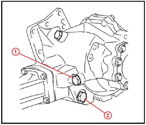
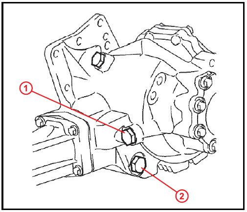
- Remove the transfer case No. 1 plug and remove the gasket from the plug.
Figure 3.
| 1 | No. 1 Plug | |
| 2 | Drain Plug | |
- Remove the transfer drain plug and remove the gasket from the drain plug.
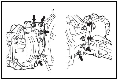
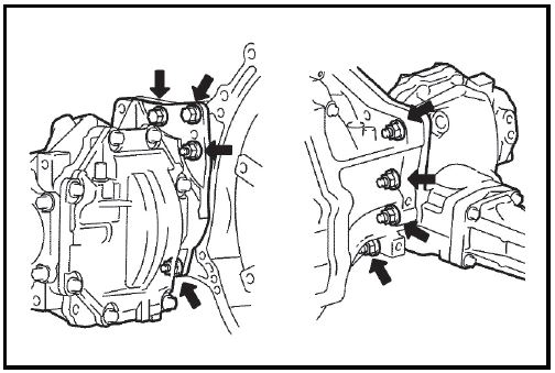
- Remove the transfer assembly.
A. Remove the 2 bolts and 6 nuts.
B. Using a plastic hammer, drive out the transfer assembly from the transaxle assembly.
NOTICE
|
Figure 4.
- Remove the transfer cover gasket from the transfer assembly.
Figure 5.
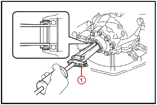
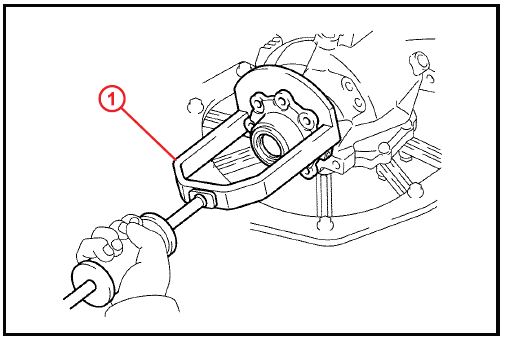
- Using the SST, remove the transfer RH bearing retainer oil seal.
SST P/N 09308-00010
| NOTICE
Be careful NOT to damage the oil-seal-fitted surface of the retainer. |
Figure 6.
| 1 | SST |
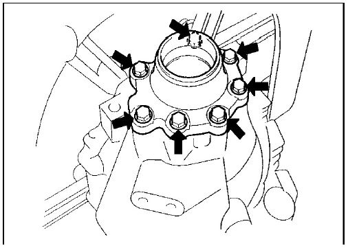
- Remove the transfer RH bearing retainer sub-assembly.
A. Remove the 7 bolts from the RH bearing retainer sub-assembly.
Figure 7.
B. Using the SST, make a clearance between the RH bearing retainer sub-assembly and the transfer case.
SST P/N 09950-00020
Figure 8.
| 1 | SST |
C. Remove the SST.
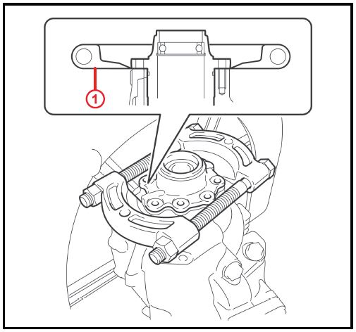
D. Using the SST, remove the RH bearing retainer Figure 9. sub-assembly from the transfer case.
SST P/N 09520-10021
Figure 9.
| 1 | SST |
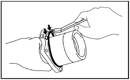
- Remove the two O-rings.
Using a plastic pry tool or equivalent, remove the two (2) O-rings from the RH bearing retainer.
NOTICE
Be careful NOT to damage the retainer’s groove for the O-ring.
Figure 10.
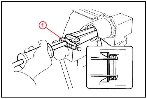
- Remove the center differential case tapered roller bearing RH (outer race).
A. Hold the RH bearing retainer in a vise.
B. Using the SST, remove the outer race, washer, and No. 2 oil seal from the RH bearing retainer.
SST P/N 09308-00010
NOTICE
Be careful NOT to damage the oil-seal-fitted surface of the retainer.
Figure 11.
Repair Procedure: Installation
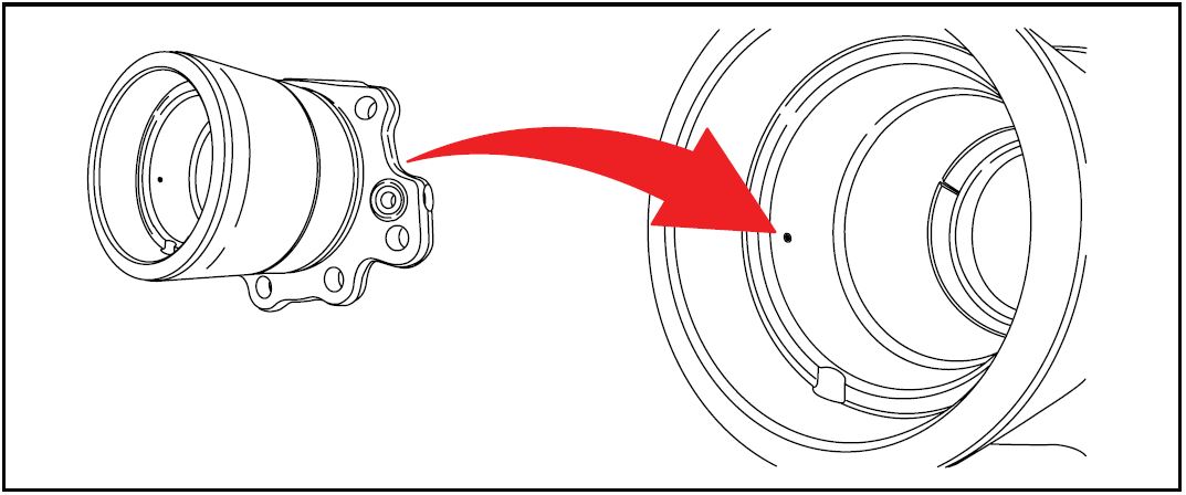
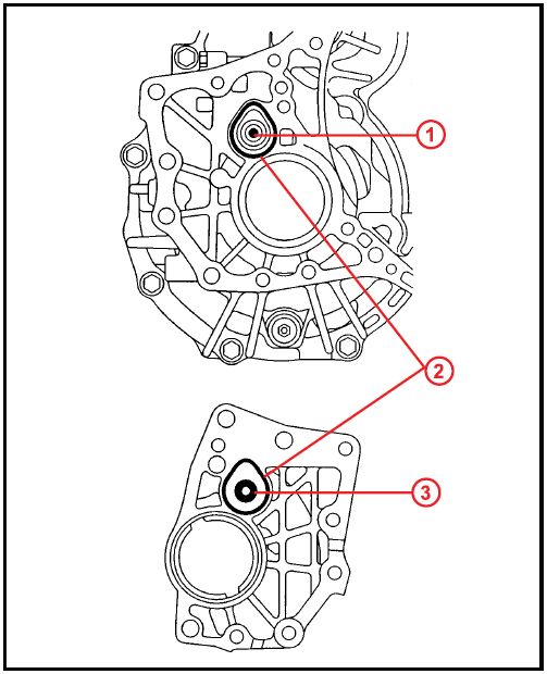
- Install a NEW No. 2 oil seal in the RH bearing retainer.
NOTE
The No. 2 oil seal MUST be positioned so that the seal is aligned over the hole located inside the RH bearing retainer. Failure to properly align the seal so that it seals on BOTH sides of the hole (vent) will cause the transfer case to leak fluid out of the vent assembly on the RH bearing retainer.
Figure 12.
NOTE
Only the outer race of the center differential case tapered roller bearing is to be replaced with a NEW part. Reuse of the center differential case tapered roller bearing should prevent the requirement to re-adjust driven pinion preload.
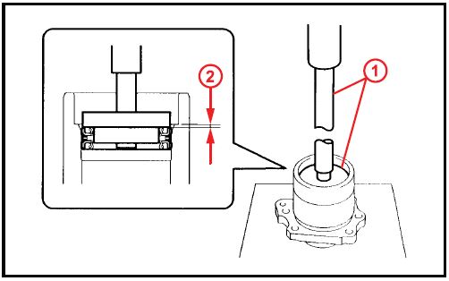
- Install the transfer RH bearing retainer oil seal No. 2.
A. Using the SST and a press, install the oil seal No. 2 to the RH bearing retainer.
SST P/N 09950-60010 (09951-00360, 09951-00540, 09952-06010), 09950-70010 (09951-07150)
| NOTE
Carefully press-fit so that the oil seal is NOT tilted. |
Figure 13.
| 1 | SST |
| 2 | 1.5 – 2.5 mm (0.059 – 0.098 in.) |
B. Apply a small amount of MP grease No. 2 to the oil seal lip.
- Install the transfer ring gear mounting case washer No. 2 to the RH bearing retainer.
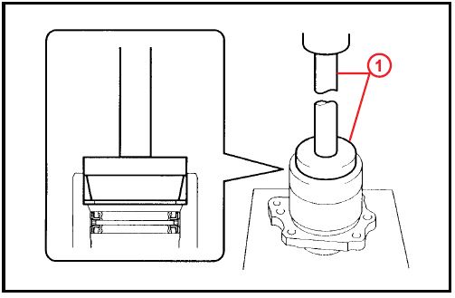
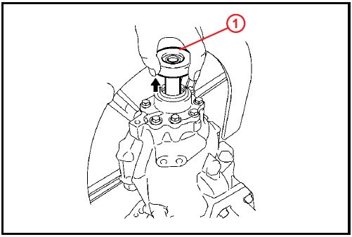
- Install the center differential case tapered roller Using the SST and a press, install the outer race to the RH bearing retainer.
SST P/N 09950-60010 (09951-00620), 09950-70010 (09951-07150)
Figure 14.
| 1 | SST |
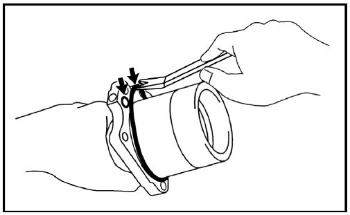
- Install the O-rings.
A. Apply Hypoid gear oil to the two NEW O-rings.
B. Install the two (2) O-rings to the RH bearing retainer.
| NOTICE
Be careful NOT to twist the O-ring and fit it into the retainer’s groove properly. |
Figure 15.
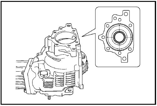
- Install the transfer RH bearing retainer sub-assembly.
A. Place the transfer case with the face where the RH bearing retainer is to be installed facing up, as shown in the illustration.
Figure 16.
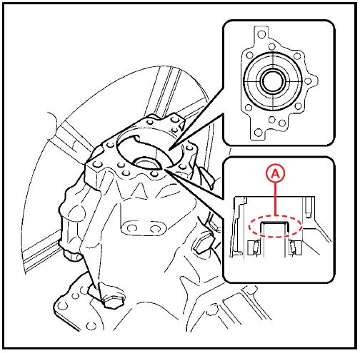
B. Center-align the center differential control coupling assembly and the case.
C. Apply MP grease No. 2 thinly to area A as shown in the illustration.
| HINT
Apply MP grease No. 2 to prevent the oil seal lip from rolling back. |
Figure 17.
| 1 | Area A |
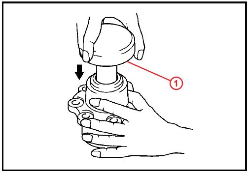
D. Insert the SST into the transfer RH bearing retainer sub-assembly. SST P/N 09387-00090
| NOTICE
Insert the SST straight in order NOT to damage the oil seal. |
Figure 18.
| 1 | SST |
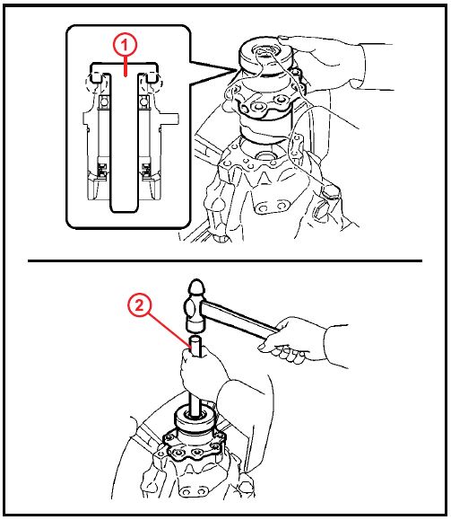
E. With the SST and the transfer RH bearing sub-assembly in close contact, install the transfer RH bearing retainer sub-assembly together with the SST into the transfer case.
NOTICE
- Avoid interference between the case and the retainer and between the SST and the transfer ring gear mounting case.
- Carefully check the retainer’s O-ring for damage and incorrect fitting.
HINT
- If the engagement is tight, tap the SST with a hammer placing a brass bar on the center of the SST.
- If the SST and retainer are NOT in close contact, the seal for the inner end of the retainer may NOT be properly aligned when the retainer goes into position. This may result in the lip of the oil seal being rolled back during installation.
- If the SST and retainer are NOT in close contact, the center of the retainer or transfer ring gear mounting case may come out of position when the retainer is being installed. This can cause the lip of the oil seal to be rolled back.
Figure 19.
| 1 | SST | |
| 2 | Brass Bar | |
F. Make sure that the transfer RH bearing retainer sub-assembly and transfer case contact closely.
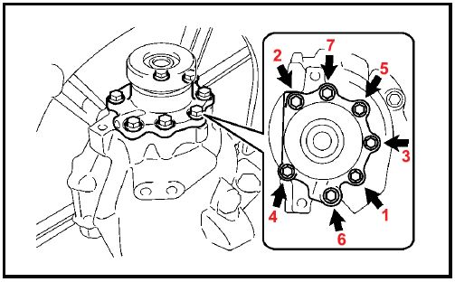
G. Tighten the 7 bolts evenly in the order shown in the illustration.
Torque: 28 N*m (286 kgf*cm, 21 ft*lbf)
Figure 20.
H. Remove the SST.
Figure 21.
| 1 | SST |
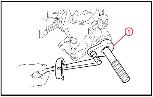
- Inspect total preload.
A. Using the SST and a torque wrench, measure the initial torque between the driven pinion bearing and the ring gear face.
SST P/N 09326-20011
Torque:
Used Bearing:
Driven Pinion Preload +0.15 – 0.30 N*m (+1.6 – 3.1 kgf*cm, +1.3 – 2.7 in*lbf)
| HINT
Use a torque wrench with a fulcrum length of 160 mm (6.30 in.). |
| NOTE
Measure the torque after rotating the bearing in both clockwise and counterclockwise directions to make it fit. |
Figure 22.
| 1 | SST |
B. If the preload is too large, replace the bearing spacer with a NEW one.
C. If the preload is too small, repeatedly adjust the preload by tightening the lock nut 5 – 10 degrees at a time until the standard value is obtained.
D. If the preload is insufficient even though the tightening torque of the lock nut exceeds the maximum of the standard value, loosen the lock nut and apply gear oil SAE 90 (GL-5) to the lock nut and the screw thread and base of the driven pinion. Then repeat the preceding operation. If the tightening torque is smaller than the standard, replace the bearing spacer with a NEW one and adjust it.
SST P/N 09326-20011, 09556-16030
Torque: 378 N*m (3855 kgf*cm, 279 ft*lbf)
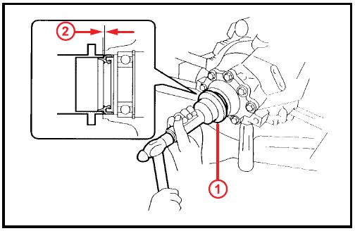
- Install the transfer RH bearing retainer oil seal.
A. Using the SST, drive the oil seal into the RH bearing retainer to the position shown in the illustration.
SST P/N 09223-46011
| NOTICE
Drive in the oil seal carefully so that it will NOT be tilted. |
B. Apply MP grease to the oil seal lip.
Figure 23.
| 1 | SST |
| 2 | 0.7 – 1.3 mm (0.028 – 0.051 in.) |
- Install a NEW transfer cover gasket to the case.
Figure 24.
- Install the transfer assembly.
A. Apply FIPG sealant 1281 to the transaxle assembly and the transfer assembly in continuous beaded form of 1.2 mm (0.05 in.) diameter as shown in the illustration.
FIPG sealant: Three Bond 1281, or equivalent
NOTICE
|
Figure 25.
| 1 | Driving Plug |
| 2 | Sealant |
| 3 | Gasket |
B. Install the transfer assembly to the transaxle assembly with the 2 bolts and 6 nuts.
Torque: 69 N*m (700 kgf*cm, 51 ft*lbf)
| NOTICE |
Figure 26.
- Install the automatic transmission w/transfer.
Refer to TIS, applicable model and model year Repair Manual:
2004 Highlander: Drivetrain – Automatic Transmission/Transaxle – “Automatic Transaxle Assy (U151E/U151F) / (U241E/U140F): Replacement”
2005 Highlander: Drivetrain – Automatic Transmission/Transaxle – “Automatic Transaxle Assy (U151E/U151F) / (U241E/U140F): Replacement”
2006 Highlander: Drivetrain – Automatic Transmission/Transaxle – “U140F / U151F Automatic Transaxle: Automatic Transaxle Assembly: Installation”
2007 Highlander: Drivetrain – Automatic Transmission/Transaxle – “U140F / U151F Automatic Transaxle: Automatic Transaxle Assembly: Installation”
2008 / 2009 Highlander: Drivetrain – Automatic Transmission/Transaxle – “U151F Automatic Transaxle: Automatic Transaxle Assembly: Installation”
2001 / 2002 / 2003 / 2004 / 2005 RAV4: Drivetrain – Automatic Transmission/Transaxle – “Automatic Transaxle Unit (U140F): Installation”
2004 / 2005 Sienna: Drivetrain – Automatic Transmission/Transaxle – “Automatic Transaxle Assy (U151E/U151F): Replacement”
2006 / 2007 / 2008 / 2009 / 2010 Sienna: Drivetrain – Automatic Transmission/Transaxle – “U151F Automatic Transaxle: Automatic Transaxle Assembly: Installation”
Refer to TIS, applicable model and model year Repair Manual:
2004 Highlander: Engine/Hybrid System – Engine Mechanical – “2AZ-FE / 3MZ-FE: Partial Engine Assy: Replacement”
2005 Highlander: Engine/Hybrid System – Engine Mechanical – “2AZ-FE / 3MZ-FE: Partial Engine Assy: Replacement”
2006 Highlander: Engine/Hybrid System – Engine Mechanical – “2AZ-FE / 3MZ-FE Engine Mechanical: Engine Assembly: Installation”
2007 Highlander: Engine/Hybrid System – Engine Mechanical – “2AZ-FE / 3MZ-FE Engine Mechanical: Engine Assembly: Installation”
2008 / 2009 Highlander: Engine/Hybrid System – Engine Mechanical – “ 2GR-FE Engine Mechanical: Engine Assembly: Installation”
2001 / 2002 / 2003 / 2004 / 2005 RAV4: Engine/Hybrid System – Engine Mechanical – “Engine Unit: Installation”
2004 / 2005 Sienna: Engine/Hybrid System – Engine Mechanical – “Partial Engine Assy: Replacement”
2006 Sienna: Engine/Hybrid System – Engine Mechanical – “3MZ-FE Engine Mechanical: Engine Assembly: Installation”
2007 / 2008 / 2009 / 2010 Sienna: Engine/Hybrid System – Engine Mechanical – “2GR-FE Engine Mechanical: Engine Assembly: Installation”
- Install the transfer drain plug with a NEW gasket. Torque: 49 N*m (500 kgf*cm, 36 ft*lbf)
Figure 27.
| 1 | No. 1 Plug |
| 2 | Drain Plug |
- Install the transfer case No. 1 plug.
A. Add oil up to the level 0 – 5 mm (0 – 0.20 in.) below the lowest end of the plug hole.
Oil quantity:
0.95 U.S. qts (0.9 L, 0.71 lmp. qts)
NOTE
Add oil slowly.
B. Install the No. 1 plug with a NEW gasket.
Torque: 49 N*m (500 kgf*cm, 36 ft*lbf)
- Inspect and adjust front wheel alignment.
Refer to TIS, applicable model and model year Repair Manual:
2004 / 2005 Highlander: Suspension – Alignment/Handling Diagnoses – “Front Wheel Alignment: Adjustment”
2006 / 2007 / 2008 / 2009 Highlander: Suspension – Alignment/Handling Diagnoses – “Suspension: Front Wheel Alignment: Adjustment”
2001 / 2002 / 2003 / 2004 / 2005 RAV4: Suspension – Alignment/Handling Diagnoses – “Front Wheel Alignment: Inspection”
2004 / 2005 Sienna: Suspension – Alignment/Handling Diagnoses – “Front Wheel Alignment: Adjustment”
2006 / 2007 / 2008 / 2009 / 2010 Sienna: Suspension – Alignment/Handling Diagnoses – “Suspension: Front Wheel Alignment: Adjustment”
Refer to TIS, applicable model and model year Repair Manual: 2004 / 2005 Highlander:
Brake – Brake Control/Dynamic Control System – “ABS With EBD & BA & TRAC & VSC System: Pre-Check”
2006 / 2007 / 2008 / 2009 Highlander: Brake – Brake Control/Dynamic Control System – “Brake Control: Vehicle Stability Control System: Test Mode Procedure”
2001 / 2002 / 2003 / 2004 / 2005 RAV4: Brake – Brake Control/Dynamic Control System – “Anti-Lock Brake System With Electronic Brake Force Distribution (EBD): Pre-Check”
2004 / 2005 Sienna: Brake – Brake Control/Dynamic Control System – “ABS With EBD & BA & TRAC & VSC System: Pre-Check”
2006 / 2007 / 2008 / 2009 / 2010 Sienna: Brake – Brake Control/Dynamic Control System – “Brake Control: Anti-lock Brake System: Test Mode Procedure”
- Re-initialize any affected power systems.
Refer to TIS for the applicable TSB or Repair Manual section.
 Loading...
