| “This site contains affiliate links for which OEMDTC may be compensated” |
T-SB-0253-08
August 14, 2008
Front Power Seat Grinding / Groaning Noise
| Service Category | Vehicle Interior | ||
|---|---|---|---|
| Section | Seat | Market | USA |
Applicability
| YEAR(S) | MODEL(S) | ADDITIONAL INFORMATION |
|---|---|---|
| 2005 – 2009 | Avalon | WMI(s): 4T1 |
| 2007 – 2009 | Camry HV | WMI(s): 4T1 |
| 2002 – 2009 | Camry | WMI(s): 4T1, 4T4 |
| 2009 | Corolla | WMI(s): 1NX, 2T1 |
| 2005 – 2008 | Sequoia | WMI(s): 5TD |
| 2004 – 2008 | Sienna | WMI(s): 5TD |
| 2004 – 2008 | Solara | WMI(s): 4T1 |
| 2005 – 2008 | Tundra | WMI(s): 5TB, 5TF |
Introduction
Some owners of North American produced (NAP) Toyota vehicles may complain that their front power seat makes a grinding/groaning noise when adjusting the seat forward or backward. To correct this condition and to enhance serviceability, an improved motor assembly is now available as a separate service part. Please refer to the repair procedure to address customer concerns.
Warranty Information
| OP CODE | DESCRIPTION | TIME | OFP | T1 | T2 |
|---|---|---|---|---|---|
| BO8003 | R & R Fore & Aft Seat Motor (Either side) | 1.0 | 71200–##### | 91 | 43 |
| Combo A | Opposite Side | 0.8 |
APPLICABLE WARRANTY
|
Parts Information
| MODEL | MODEL YEAR | PREVIOUS PART NUMBER | CURRENT PART NUMBER | PART NAME | QTY |
|---|---|---|---|---|---|
| Avalon | 2005–2009 | N/A | 85820-06080 | Motor Assembly, Power Seat (LH) | 1 |
| Camry | 2002–2009 | 1 | |||
| Corolla | 2009 | 1 | |||
| Sequoia | 2005–2007 | 1 | |||
| Sienna | 2004–2008 | 1 | |||
| Solara | 2004–2008 | 1 | |||
| Tundra | 2005–2006 | 1 | |||
| Avalon | 2005–2009 | N/A | 85820-06070 | Motor Assembly, Power Seat (RH) | 1 |
| Camry | 2002–2009 | 1 | |||
| Corolla | 2009 | 1 | |||
| Sequoia | 2005–2007 | 1 | |||
| Sienna | 2004–2008 | 1 | |||
| Solara | 2004–2008 | 1 | |||
| Tundra | 2005–2006 | 1 | |||
| Tundra | 2007–2008 | N/A | 85820-0C010 | Motor Assembly, Power Seat (RH) | 1 |
| Sequoia | 2008 | 1 | |||
| Tundra | 2007–2008 | N/A | 85820-0C020 | Motor Assembly, Power Seat (LH) | 1 |
| Sequoia | 2008 | 1 |
Required Tools & Equipment
| SPECIAL SERVICE TOOLS (SST’S) | PART NUMBER | QTY |
|---|---|---|
| Plastic Pry Tool Set* | 00002-06000-01 | 1 |
* Essential SST.
| NOTE
Additional SSTs may be ordered by calling SPX/OTC at 1-800-933-8335. |
Repair Procedure
NOTE
This repair procedure is typical to most applications. Some differences may exist between models. Please refer to the appropriate section in the Repair Manual for additional details.
NOTICE
Seat motor/gear drive assembly MUST be replaced with the seat bolted to the floor to prevent misalignment of the left and right track guides.
- Adjust the seat to the full rear position and remove the front bolts that hold the seat to the floor.
Remove any garnishes over the bolts if present.
- Adjust the seat to the full forward position and remove the rear bolts that hold the seat to the floor.
Remove any garnishes over the bolts if present.
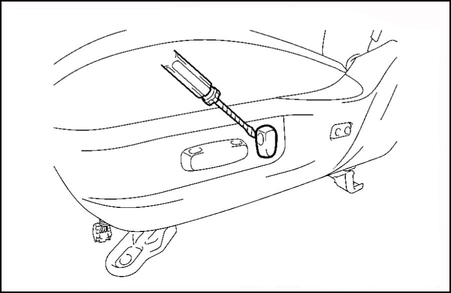
- Using a screwdriver, remove the power reclining Figure 1. and slide switches.
| HINT
Tape the screwdriver tip before use. |
Figure 1.
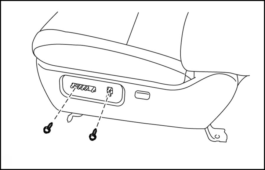
- Remove the two screws that are behind the seats witches.
Figure 2.
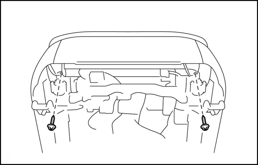
| HINT
Tip the seat back for easier access. |
Figure 3.
HINT
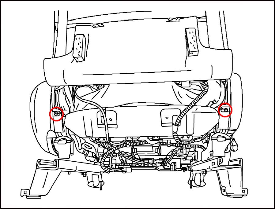
Remove the headrest and shift the entire seat towards the rear of the vehicle 6 inches (15.24 cm) to gain clearance to tip the seat.
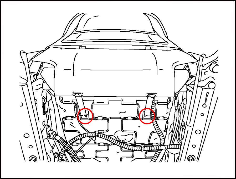
Figure 4.
Figure 5.
- Disconnect the electrical connector for the lumbar switch and remove the seat trim garnish.
- Reinstall the seat to the floor and hand tighten all 4 mounting bolts to prevent the seat from moving.
| NOTICE
Seat motor/gear drive assembly MUST be replaced with the seat bolted to the floor to prevent misalignment of the left and right track guides. |
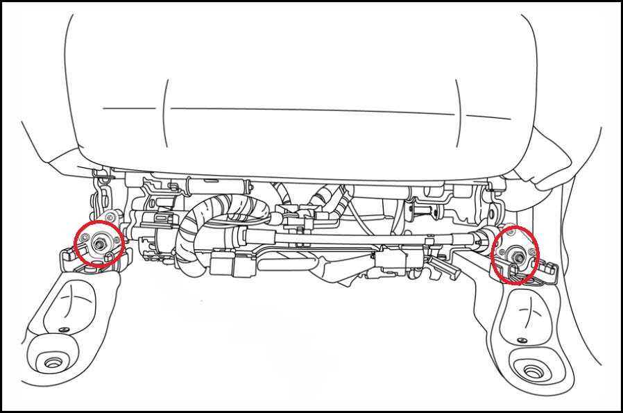
- With the seat in the full forward position, loosen the two 12-mm nuts at the front of the seat track as shown.
| NOTE
Do NOT remove the nuts. |
Figure 6.
- Move the seat to the full rear position, then remove the two nuts.
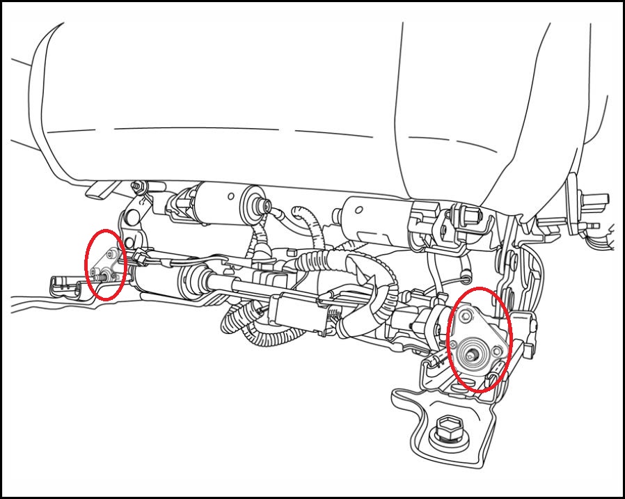
- Remove the 4 allen bolts securing the motor gearboxes to the seat as shown.
| NOTE
There are two bolts on each side. |
Figure 7.
- Disconnect the connector to the motor.
- Remove the motor and gear box assembly.
- Remove the two washers located behind the gearbox on each side.
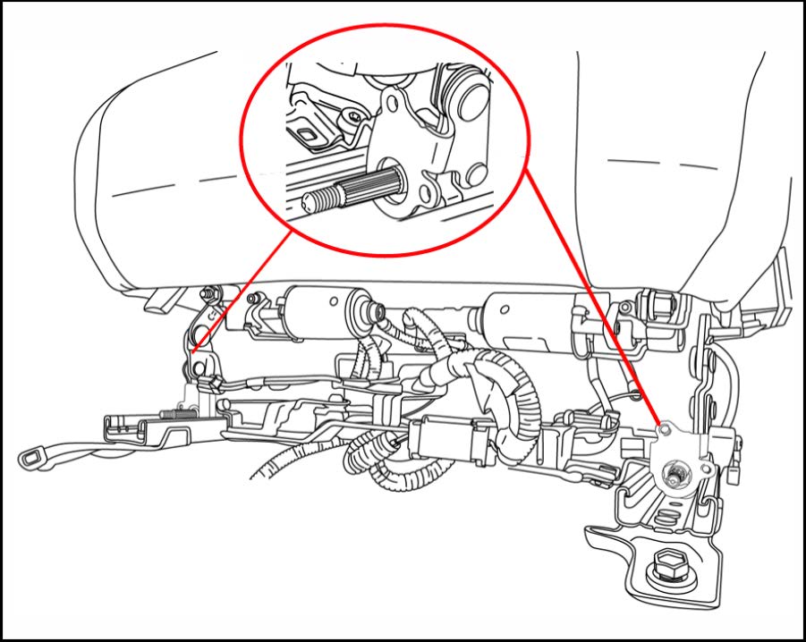
- Turn both splined shafts fully clockwise (1/4 turn or less) to take up any slack and align the shafts.
| NOTE
In some instances, there may not be any slack. |
Figure 8.
- Install the NEW washers on the shafts and install the new motor/gearbox sub-assembly with the NEW hardware.
| IMPORTANT
Proper torque is critical to component operation and longevity. Be sure to use an appropriate inch-pound torque wrench. |
- Torque the 4 allen screws.
Torque: 4 N*m (41 kgf*cm, 35 in*lbf)
- Torque the 12-mm nuts.
Torque: 3.4 N*m (35 kgf*cm, 30 in*lbf)
- Remove the bolts holding the seat to the floor.
- Reassemble the remaining seat components in reverse order.
- Reinstall the seat to the floor and replace any garnishes removed. Torque: 37 N*m (377 kgf*cm, 27 ft*lbf)
- Operate the seat several times to check for proper function and verify the noise is no longer present.
 Loading...
